


ZKC127 Mine explosion-proof electric control switch device
HomeProducts Center
- Mine Car & Construction Truck
- Belt Conveyor
- Scraper Conveyer
- Rock Loader
- Scraper Rock Loader
- Coal Mining Machine
- Road header
- Mine Car Dumper
- Shaking Table,Car Pusher
- Detritus Equipment
- Drilling Equipment
- Mine Drilling Machine
- Drilling Rod,Drilling Bits
- Water well drilling rig
- Rail Arrester
- Rail Transit Equipment
- Railroad tie
- Railway Maintenance Tools
- Railway Parts
- Track Switch
Large Equipment
Transportation Equipment
Supporting Equipment
Lifting Equipment
Guniting Equipment
Chemical Equipment
Mine Door
Rock Drilling Equipment
Ventilation&Guard Equipment
Safe&Protection Instrument
Pumping Equipment
Steel Products
Railway Materials
Explosion Proof Instrument
Electric Motor
Instrument And Meter
ZKC127 Mine explosion-proof electric control switch device
Other Names:
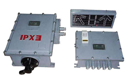
Device is composed of a controller, the electric switch machines, transmitters, monitors and other parts
Related Products- info@bstchina.group
- 0537-7768777
- Please Leave a Message
Product Detail:
Product Introduction
Product Detail:
ZKC127 Mine explosion-proof electric control switch device
Device is composed of a controller, the electric switch machines, transmitters, monitors and other parts
ZKC127 Mine explosion-proof electric control switch device Features
(1) the controller USES the anti-jamming ability of the single chip microcomputer is used to identify the signal acquisition can judge the wireless remote control at a distance to accurately control the safety of the locomotive driving switch;
(2) the digital coding technology system anti-interference ability is strong;
(3) display visually indicating the position switch the driver which can be controlled according to the locomotive target direction in the distance change switch open position; (4) high brightness generous beauty of font display switch position accurately and clearly.
ZKC127 Mine explosion-proof electric control switch device Application
The device is suitable for the coal mine, the coal, mine, bottom, and the transport roadway of centralized control and single control switch.
ZKC127 Mine explosion-proof electric control switch device Parameters
(1)the environment temperature 0 °C ~ + 40 °C.
(2) the relative humidity: 96% or less (25 °C);
(3)installed in the water, drop of severe vibration;
(4)in the gas explosive mixture, but no damage of the insulation gas or vapor atmospheres of mine.
(5)working voltage: AC127V 50Hz;
(6)explosion-proof type: mine explosion-proof and intrinsically safe explosion-proof marks: Exd (ib) I.
ZKC127 Mine explosion-proof electric control switch device Work Principle
ZKC127 Mine explosion-proof electric control switch device uses digital codec and micro control identification and other advanced technology design and is mainly composed of the remote control, receiver, microcontroller (MCU), servo system, in place of sensor and display and so on six big parts of micro-controller is the core control.Digital coding signal from nine different coding transmitter can represent the adjacent 9 need to control switch. Digital receiver receives the digital signal transmitter and in micro controller to control the complete different switch recognition in order to ensure the control switch is not action. In position sensors will complete switch in position detection display will show the code switch, switch state and device fault information currently in place.
Switch code with red number indicates a single number each corresponding to a set of switch. Switch the current state is to point to the location of the switch is open state namely straight, fork respectively with marked the green arrow "write" and "-" said. Fault information with black screen instructions.
Working principle is as follows: after the system is powered on, first of all, if a complete self-inspection self-inspection will be on display shows not normal fault indicator; If self-checking normal system is in working condition. When the car into the scope of digital receiver to receive after the driver through the display code on the display (1, 2, 3, 4... 9) on the remote control and the switch code corresponding to the keys at this time digital receiver after receiving the digital coding switch code sent the microcontroller system for digital identification; Confirmed after the success of micro controller system to switch drive issue instructions to switch drive action in place at the same time by the sensor to detect the switch location information. If the switch is not reach the designated position controller issued a directive switch drive reverse course. At this time should check inside the switch with sundry cleared again after the operation such as a remote control system can resume normal work at the same time display will show the switch position at present. This system in the controller device is optional manual button to complete the manual switch switch operation in case of lack of remote control voltage caused by not normal for the remote control when emergency treatment to ensure system reliable operation.
Product Feedback
History Feedback: (0)
Latest Feedback